Build Chassis
Add HEBI_Hexapod_Chassis Subsystem
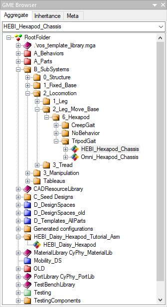
Locate the GME Browser window.
Right-click on the RootFolder > B_SubSystems > 2_Locomotion > 2_Leg_Move_Base > 6_Hexapod > TripodGait > HEBI_Hexapod_Chassis Component Assembly and select .
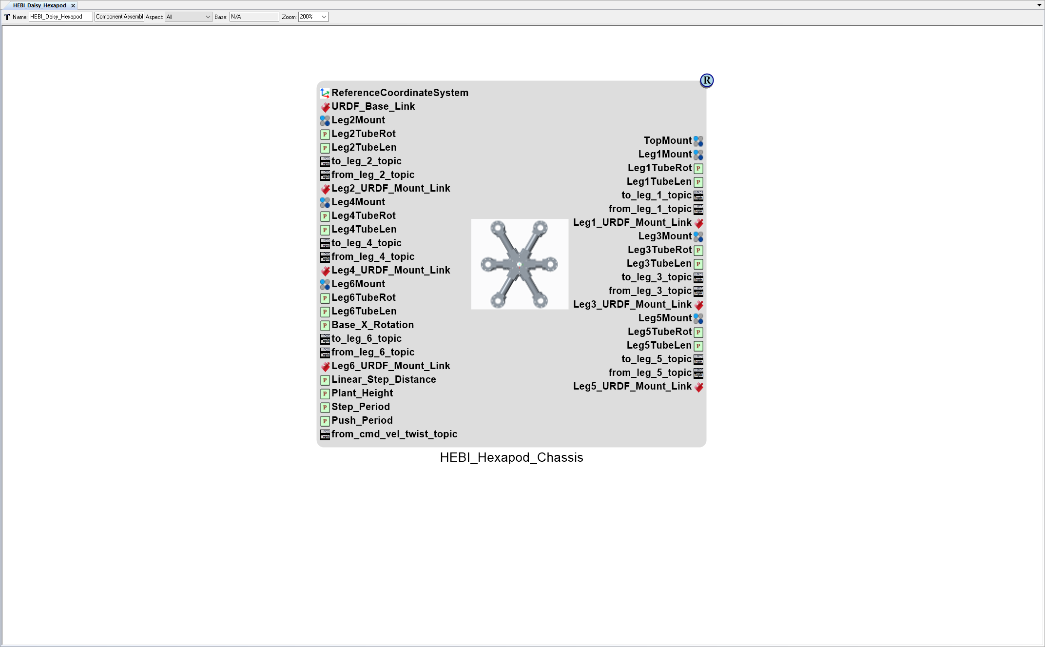
Inside the HEBI_Daisy_Hexapod Component Assembly canvas, right-click and select .
Preview in Meta-Link
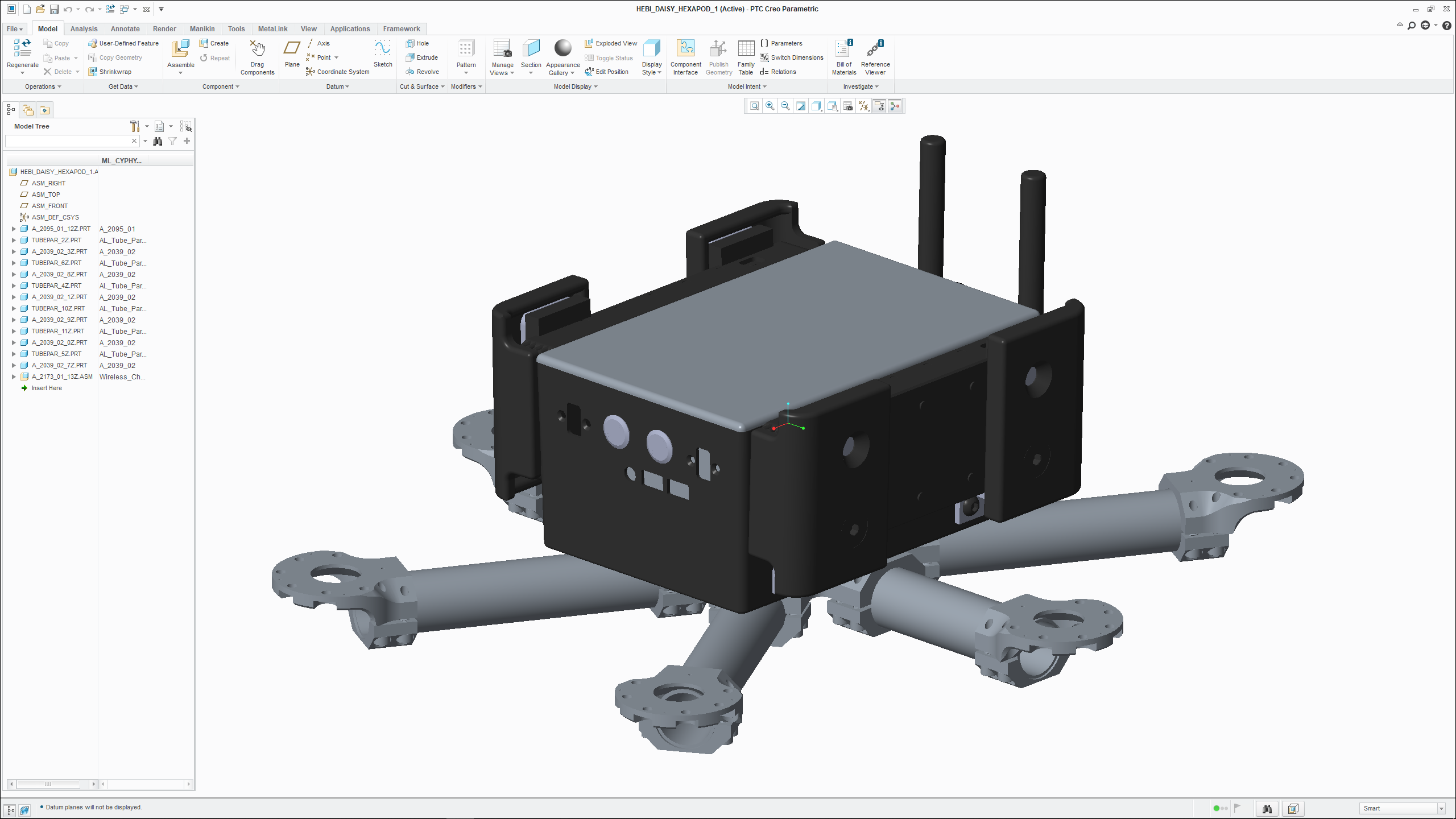
Now, the HEBI_Daisy_Hexapod System contains a single Subsystem. The physical architecture can be previewed in CREO via Meta-Link.
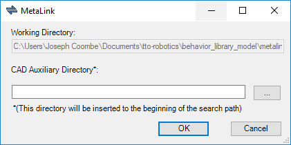
With the HEBI_Daisy_Hexapod Component Assembly canvas open, left-click on the Meta-Link button.

If the MetaLink window opens, left-click OK.
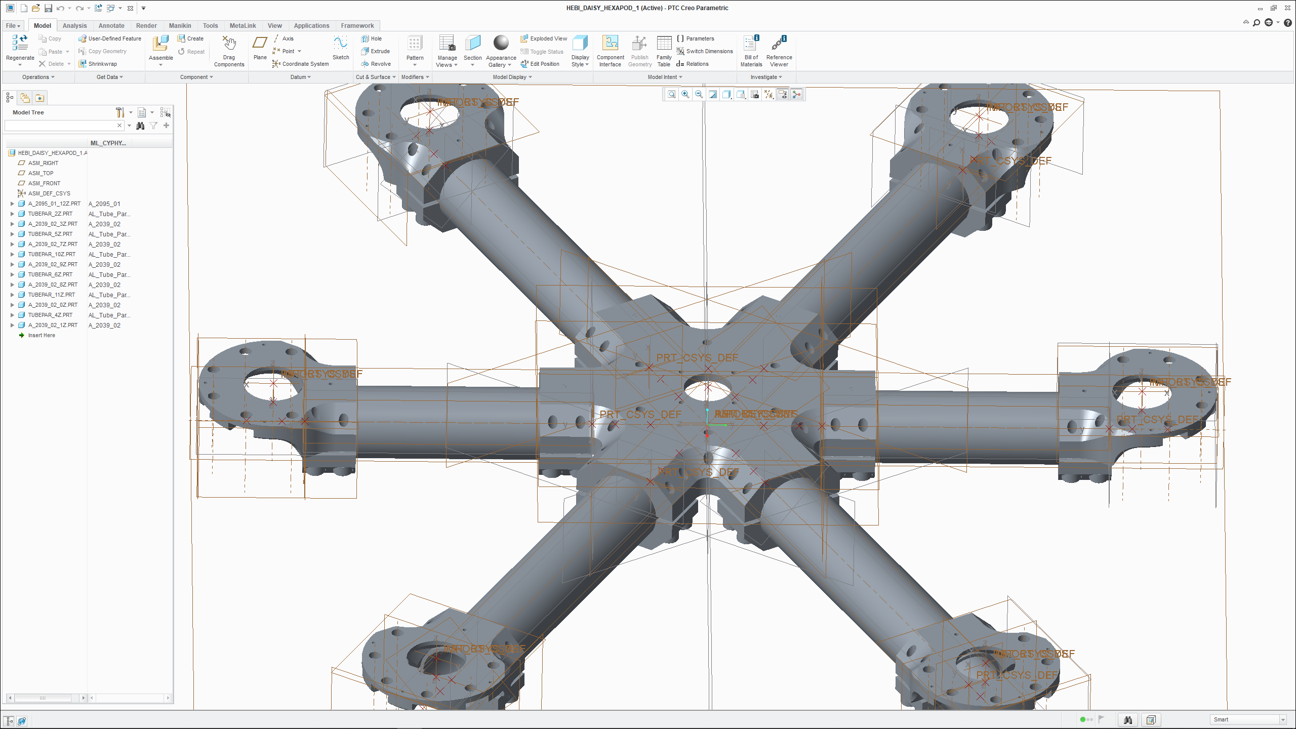
CREO will open with the composed physical model loaded.
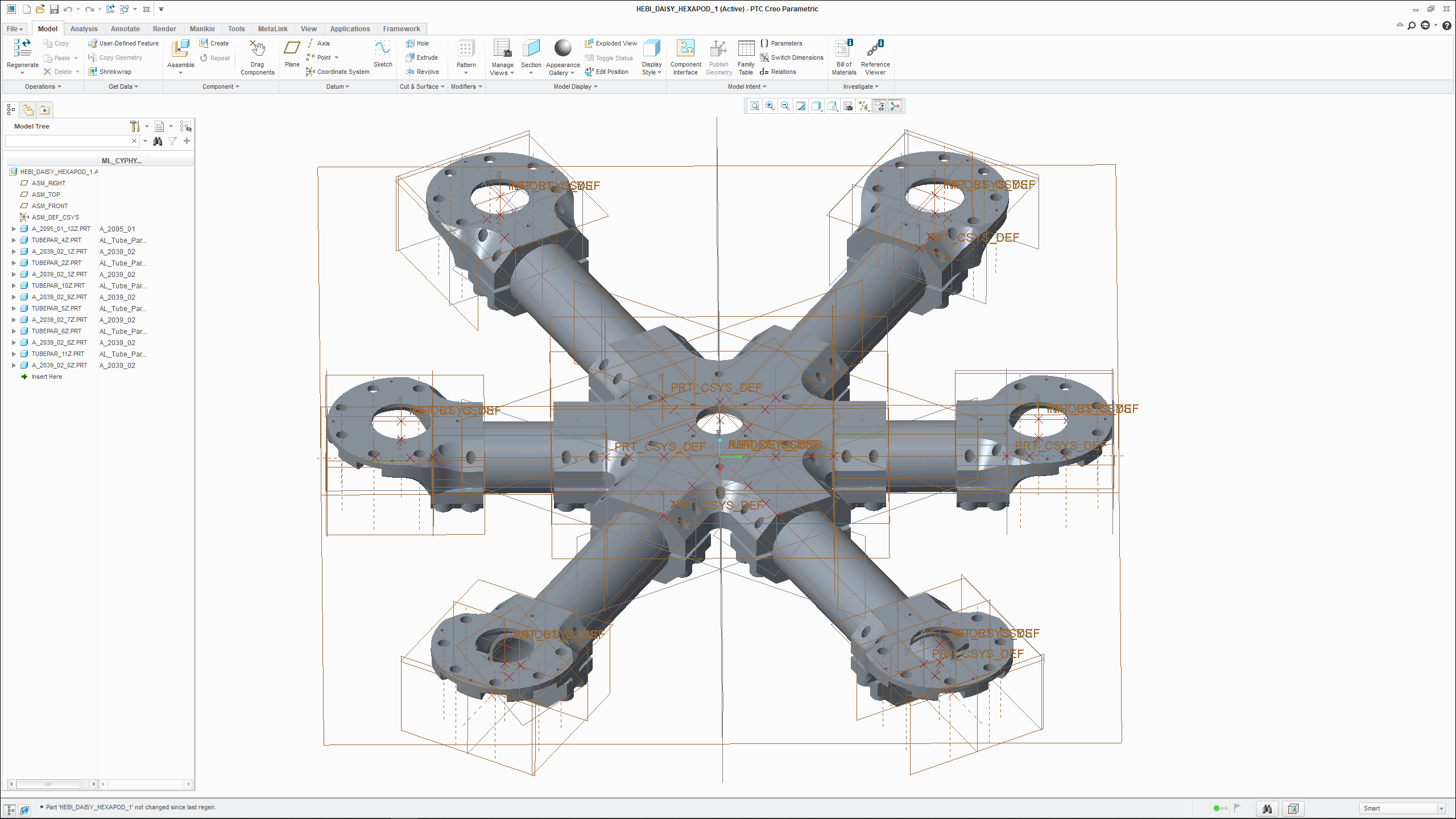
Once you’ve finished looking at the physical model, simply close CREO to exit Meta-Link.
Change HEBI_Hexapod_Chassis Tube Lengths
Let’s increase the length of the 6 tubes in HEBI_Hexapod_Chassis. One option is to modify the component directly; however, that would affect every design that contains a reference to HEBI_Hexapod_Chassis.
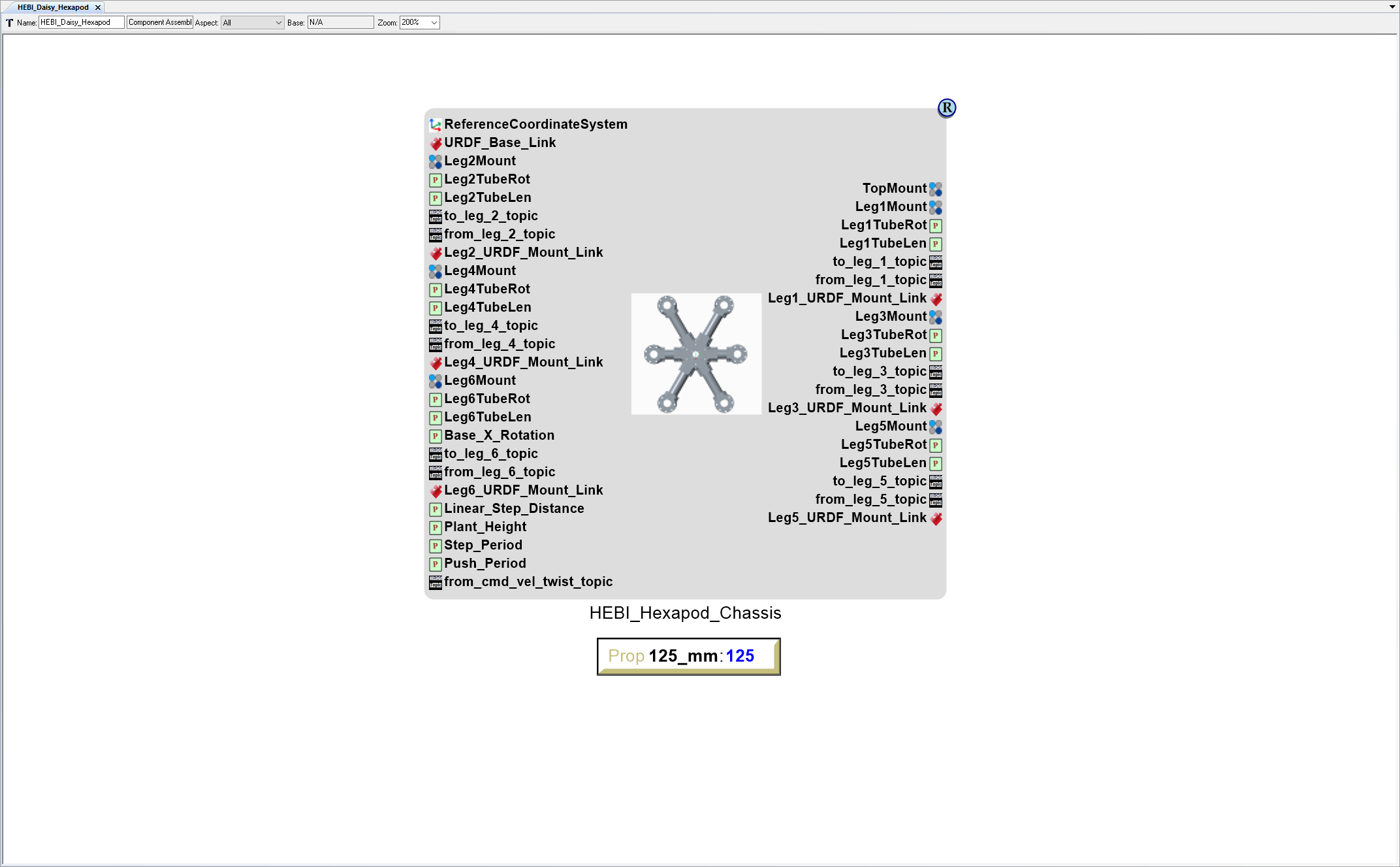
Fortunately, the HEBI_Hexapod_Chassis has a number of exposed parameter ports - including some that control the length of the 6 tubes.
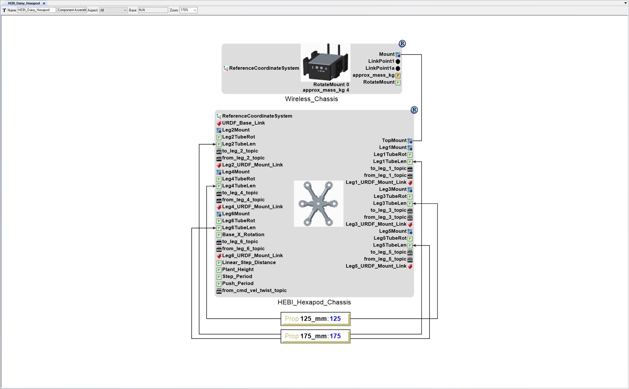
With the HEBI_Daisy_Hexapod Component Assembly canvas open, right-click on the canvas just below the HEBI_Hexapod_Chassis model and select .
Name the Property 125_mm.
Set the Property Value to 125.
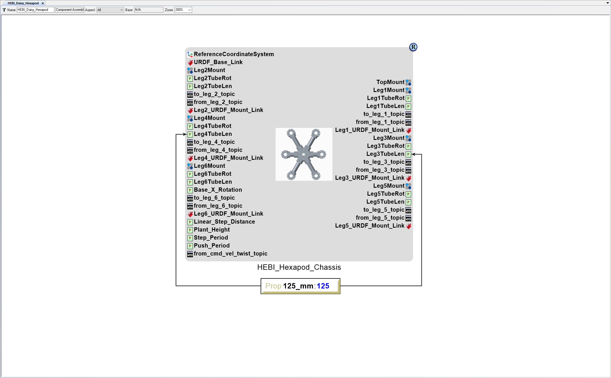
Now connect the 125_mm Property to the HEBI_Hexapod_Chassis model’s Leg3TubeLen and Leg4TubeLen Parameter ports.
Left-click Connect Mode on the Mode toolbar (alternatively press Ctrl-2 to activate Connect Mode).
Left-click on the edge of the 125_mm Property.
Then left-click on the HEBI_Hexapod_Chassis model’s Leg3TubeLen.
Left-click on the edge of the 125_mm Property.
Then left-click on the HEBI_Hexapod_Chassis model’s Leg4TubeLen.
Left-click Edit Mode on the Mode toolbar (alternatively press Ctrl-1 to activate Edit Mode).
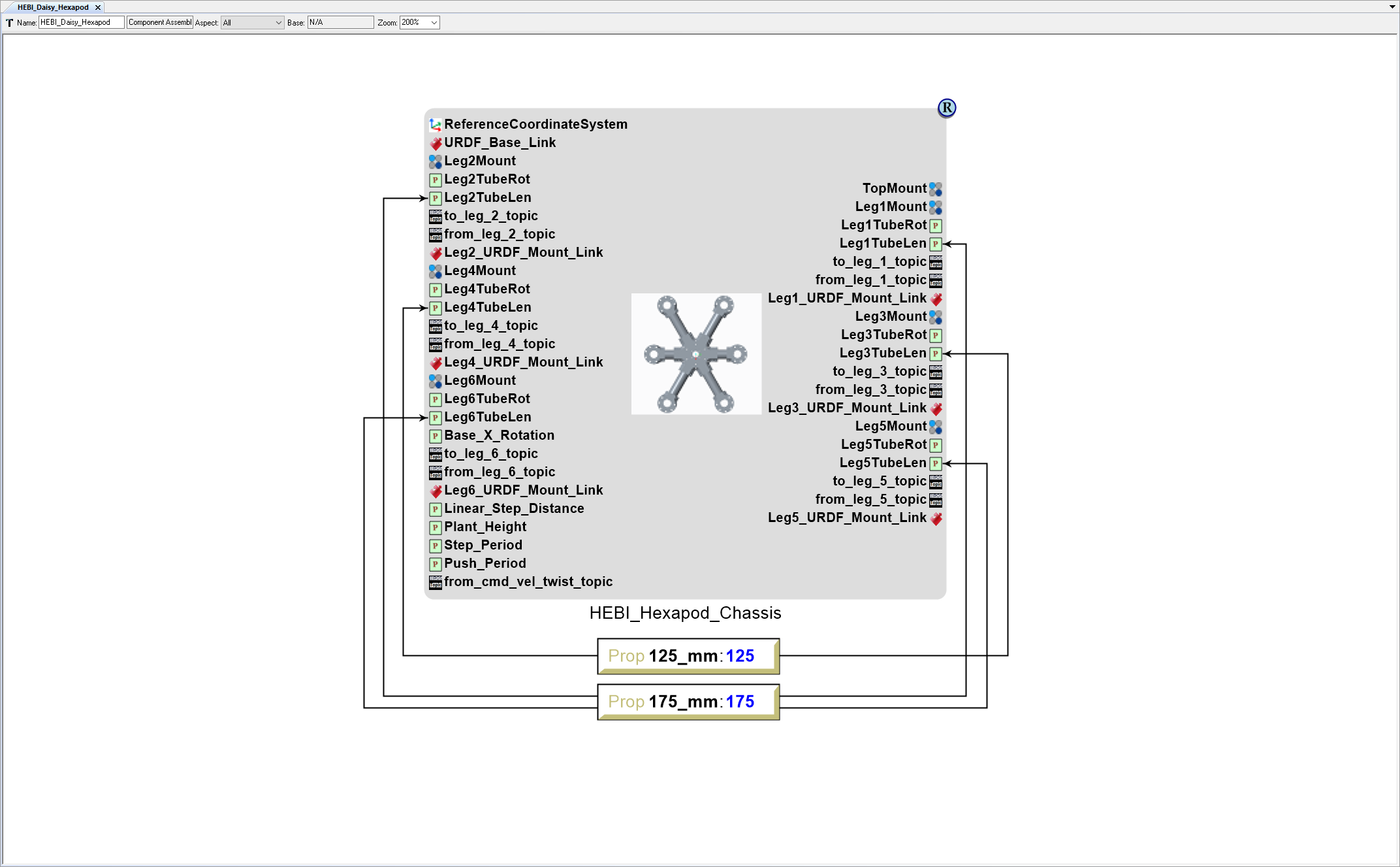
Add a second Property with a Value of 175.
- Right-click on the canvas just below the 125_mm Property and select .
- Name the Property 175_mm.
- Set the Property Value to 175.
Now connect the 175_mm Property to the HEBI_Hexapod_Chassis model’s Leg1TubeLen, Leg2TubeLen, Leg5TubeLen, Leg6TubeLen Parameter ports.
Left-click Connect Mode on the Mode toolbar (alternatively press Ctrl-2 to activate Connect Mode).
Left-click on the edge of the 175_mm Property.
Then left-click on the HEBI_Hexapod_Chassis model’s Leg1TubeLen.
Left-click on the edge of the 175_mm Property.
Then left-click on the HEBI_Hexapod_Chassis model’s Leg2TubeLen.
Left-click on the edge of the 175_mm Property.
Then left-click on the HEBI_Hexapod_Chassis model’s Leg5TubeLen.
Left-click on the edge of the 175_mm Property.
Then left-click on the HEBI_Hexapod_Chassis model’s Leg6TubeLen.
You can use Meta-Link again to verify that the physical model has changed.
Add Wireless_Chassis Part
- Locate the GME Browser window.
- Right-click on the RootFolder > A_Parts > HEBI_Robotics > 0_Chassis > Wireless_Chassis Component and select .
- Inside the HEBI_Daisy_Hexapod Component Assembly canvas, right-click and select .
Connect Wireless_Chassis Part to HEBI_Hexapod_Chassis
Left-click Connect Mode on the Mode toolbar (alternative press Ctrl-2 to activate Connect Mode).
Left-click the HEBI_Hexapod_Chassis model’s TopMount Connector port.
Then left-click on the Wireless_Chassis model’s Mount Connector port to connect the two models.
Left-click Edit Mode on the Mode toolbar (alternatively press Ctrl-1 to activate Edit Mode).
You can use Meta-Link again to verify that the physical model has changed.
Designate Root Model in Component Assembly
Now that the HEBI_Daisy_Hexapod Component Assembly contains more than 1 CADModel, you need to designate which one is the root component.
- With the HEBI_Daisy_Hexapod Component Assembly canvas open, right-click on the canvas and select .
- Left-click Connect Mode on the Mode toolbar (alternative press Ctrl-2 to activate Connect Mode).
- Left-click the ReferenceCoordinateSystem atom.
- Then left-click on the HEBI_Hexapod_Chassis model’s ReferenceCoordinateSystem port to designate the HEBI_Hexapod_Chassis as the root model in the Component Assembly.
- The Select Connection Role Type window will open. Select RefCoordSystem2RefCoordSystem and left-click OK.
- Left-click Edit Mode on the Mode toolbar (alternatively press Ctrl-1 to activate Edit Mode).